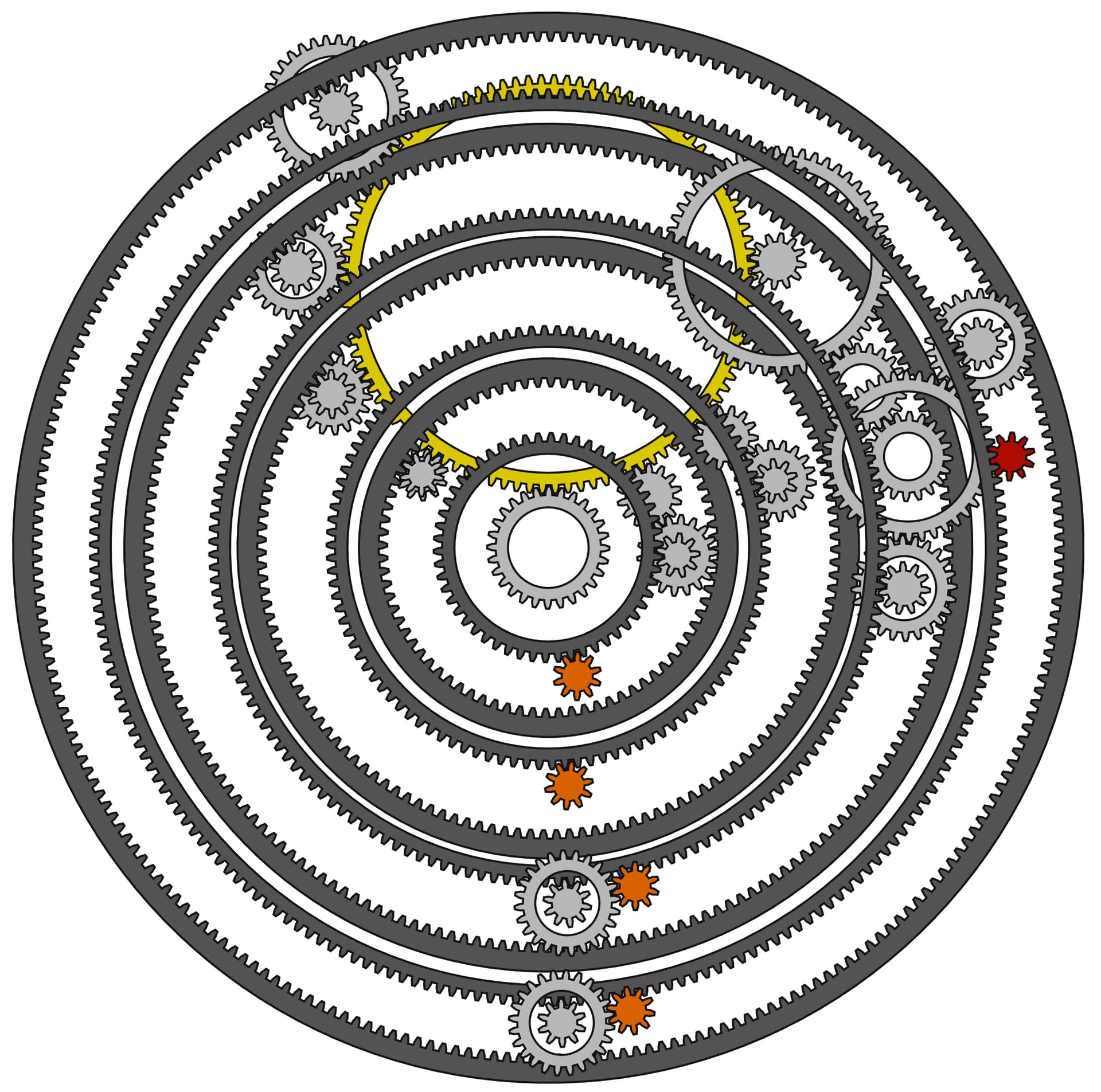
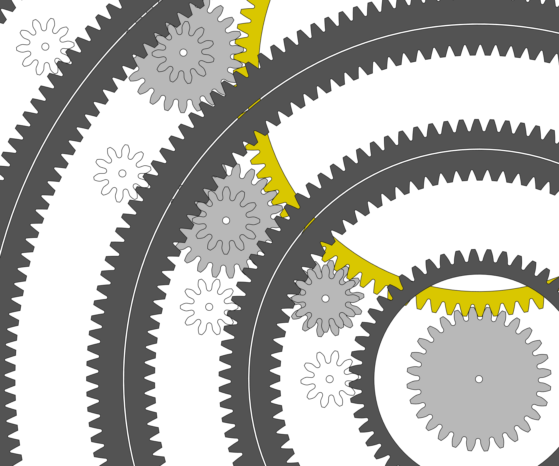
I’m trying to follow the design but it’s not completely obvious how it’s all working…
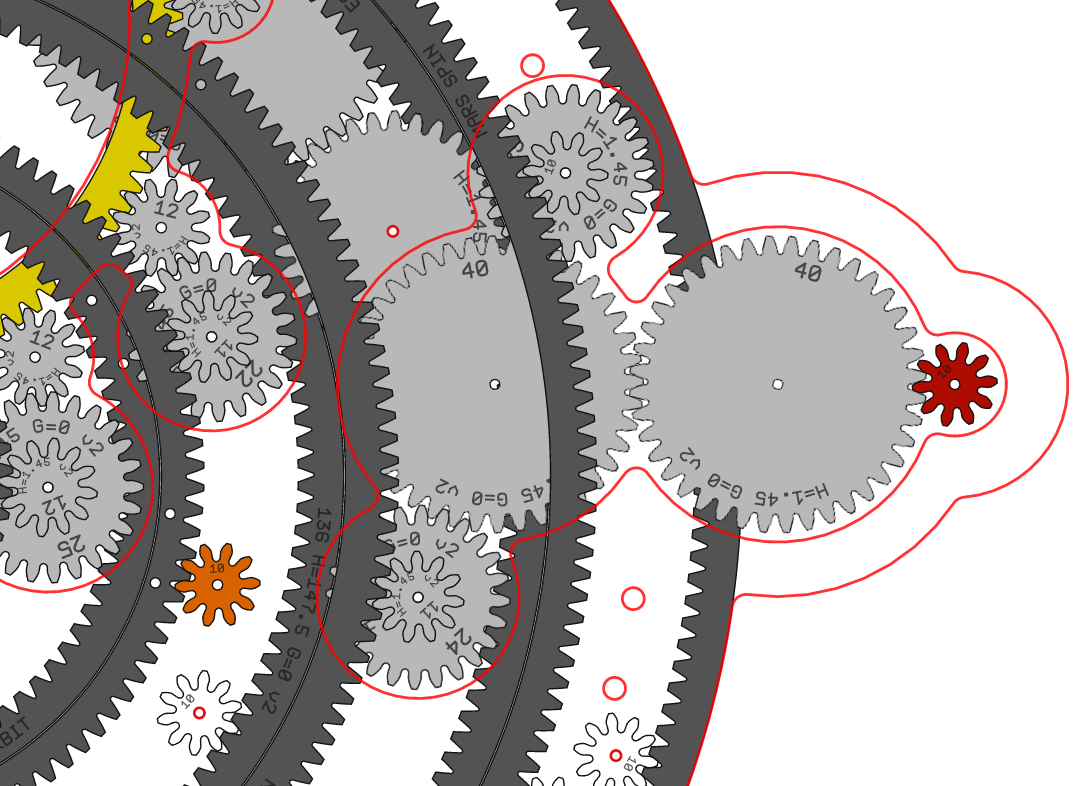
I’m assuming the central pale grey gear is driven and that in turn drives the yellow gear (or is it the other way around?). The yellow gear then drives the connected pale grey gears which then turn the dark grey rings. Presumably the planets are mounted on the dark grey rings?
How would the dark grey rings be mounted?
I’m not sure what the function of the orange, red and pale grey gears by them is - possibly something to do with planets rotating, or moons?
Anyway, looking and the design and similar projects online I’m not absolutely sure if it’s feasible or not.
I also found some youtube videos of partially successful attempts to build pendulum clocks from lasercut acrylic (which are probably similar in complexity).
It certainly would be a challenging build, and one that I’d suggest building up to. If it was me I’d probably try making a simpler orrery on the same principle first - perhaps with just the Sun, Earth, and Moon to begin with?
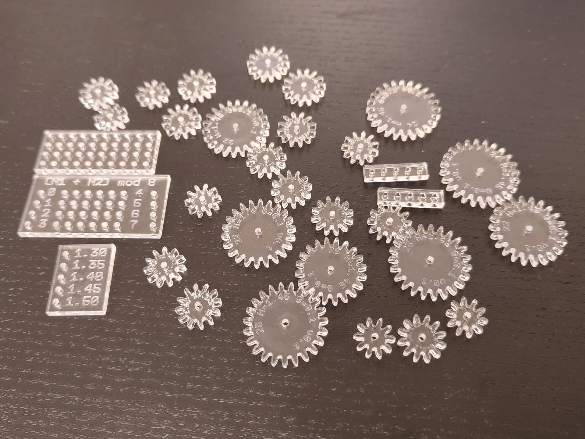
Thank you! A bit of explanation behind the design:
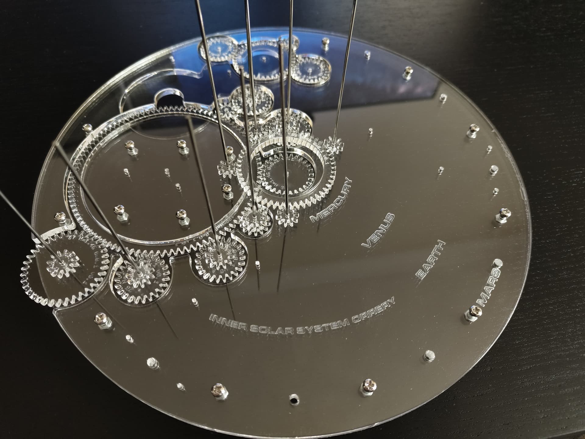
Lots of orreries have everything mounted on a “stack” in the middle and have L shaped arms reaching out. I want to see if it’s possible to make an orrery that avoids this and is mostly “flat”. My design only has three layers of gears plus the planets.
The red gear is where the crank is attached. One rotation of that is one day.
The orange gears are the planets. For each planet, there are two grey gears, one that makes the planet go around the sun and the other one is needed to make the planet spin on its own axis.
I’m not sure how the dark grey gears will be mounted. I think I could add more gears around them to keep them in place and I would rely on gravity to keep them from moving up. But it will need some experimenting to see if they have too much friction.
I had this project in mind to “build up to” more complex designs with moons and outer planets ;). Also I really want to make it out of brass but that involves very expensive materials and tools.
I’ll have limited time next week, but after that I’m hoping to meet someone in the makerspace who is familiar with the laser cutter so I can learn to use it.
For now, I’m wondering what the preferred file format is. What do I need to put in a file if I want to cut out a gear and also engrave something on it? Do I need to consider the cutting radius of the beam?
We a piece of Chinese software called RDWorks to run the laser cutter. As I remember it can import a couple of file types - DXF or SVG are what I’d probably use.
Sadly RDWorks isn’t amazing at importing files so you usually have to prepare the file a bit before saving/exporting it - exactly what you need to do depends on the software you’re coming from, and the features you’re using.
A useful basic step is to draw a rectangle around your design with a known size - this makes it a lot easier to confirm that the scale has come out as intended, and if not to correct it.
Once in RDWorks different laser settings are applied using different coloured lines (you can also use bitmaps for engraving images).
The best plan to begin with is to try to export your design in as many variants of DXF and SVG versions as your software supports and see what works.
The laptop connected to the laser cutter also has inkscape installed so you can always use that to change and re-export a design if RDWorks seems to be unhappy with it.
The amount of material removed by the laser (referred to as the kerf) usually works out at about 0.2mm. For a system of gears that may be a useful amount of spacing to allow the gears to turn smoothly without binding, so I wouldn’t worry about it to start with.
There’s also possibly minor room for improvement in the laser cutter setup. It’s pretty good at the moment but for cutting gears we might be able to get the beam a tiny bit more vertical.
It should be possible to get someone to do a laser induction session. One possibility might be after the EGM once a date has been confirmed for that.
Thanks, I’ll attend the EGM tomorrow so that I can start using the laser if someone is there to do the induction after the meeting.
The shapes are just arrays of points in my program at the moment, but I can save them into an SVG file and I’ll look into exporting DXF (although maybe SVG will just work).
Is it possible to download RDWorks anywhere? I can’t find a download but I think it would be useful to check if it accepts my files.
You should be able to find RDworks to download. There’s also a program I used I think it was called SolidWorks which has a one month free trial. I use that connected directly to the laser cutter.
I learned a lot about the measurements and will update my code so that it outputs DXF instead of SVG and get it to use the measurements we figured out today.
I saw someone on Twitter cut this with a laser cutter (6mm thickness, twice of what I’m doing):
I wonder if we can achieve similar edges with our lasercutter. Is this a matter of tuning? Or lowering the power? Or are these kinds of cuts impossible with our laser?
It should be possible to get a similar cut, adjusting the power and speed is probably the most critical part. It’s also a bit easier to get a good cut on a long straight edge than on small detailed parts.
Probably the best way to get a neater cut will be to run a variety of test cuts at different speed and power settings and see how they perform.
I’m pretty sure we could have increased the speed and still had a cut all the way through, although I’m not certain the cutter will have reached full speed on such small parts.
If the laser head isn’t reaching full speed then it may be worth dropping the min power setting down do reduce the melting.
Another option is to try less power and a couple of passes, but I don’t know how much that will help.
But I’m concerned about the large hollow gears that rest on top of the orrery. There may be too much friction and it seems that just putting gears next to them isn’t enough to keep them from sliding out of place.
Next steps:
Cutting the metal rods
Gluing metal rods and gears
Remaining gears and structural part
Figure out how to keep the large gears in place
Figure out how to attach acrylic parts to metal rods
Figure out how to prevent gears from sliding off the metal rods
At the moment it looks like I will rely on gravity to keep the parts together. If anyone has ideas on how to solve any of these, please post them!
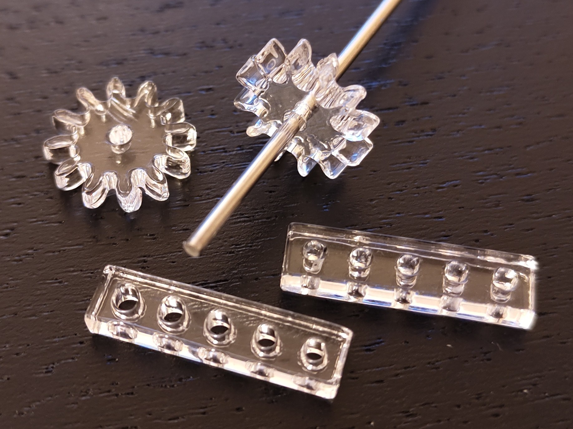
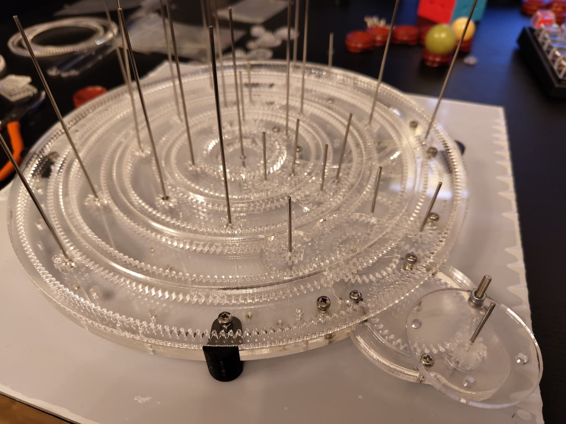
Here is an update after I cut the large gears.
Something went wrong and the underside of these large gears is cracked. The good news is that if I put them upside down, the whole mechanism works really well. I’ve got some new acrylic sheets but these are always a bit risky since you’ve got only one try per sheet to get it right for the big gears!
At the moment I’m trying to figure out how the crank handle will be attached. I’m considering an angled attachment, but a flat one like this would be easier to do:
I’ve completed the detachable crank assembly
Unfortunately, it goes counterclockwise and I’d like it to go clockwise. But since it’s detachable, I can make a new one and replace it. I’ve also bought a stepper motor so the orrery can be hand cranked and motor driven.
It turns out that the problem I had with cutting the large gears was that I was making two cuts too close to each other. So the laser was cutting into an area that was already cut and that caused a flame and created a rough surface. I’ve changed that to a single cut and I increased the gap between adjacent gears using a sander and file.
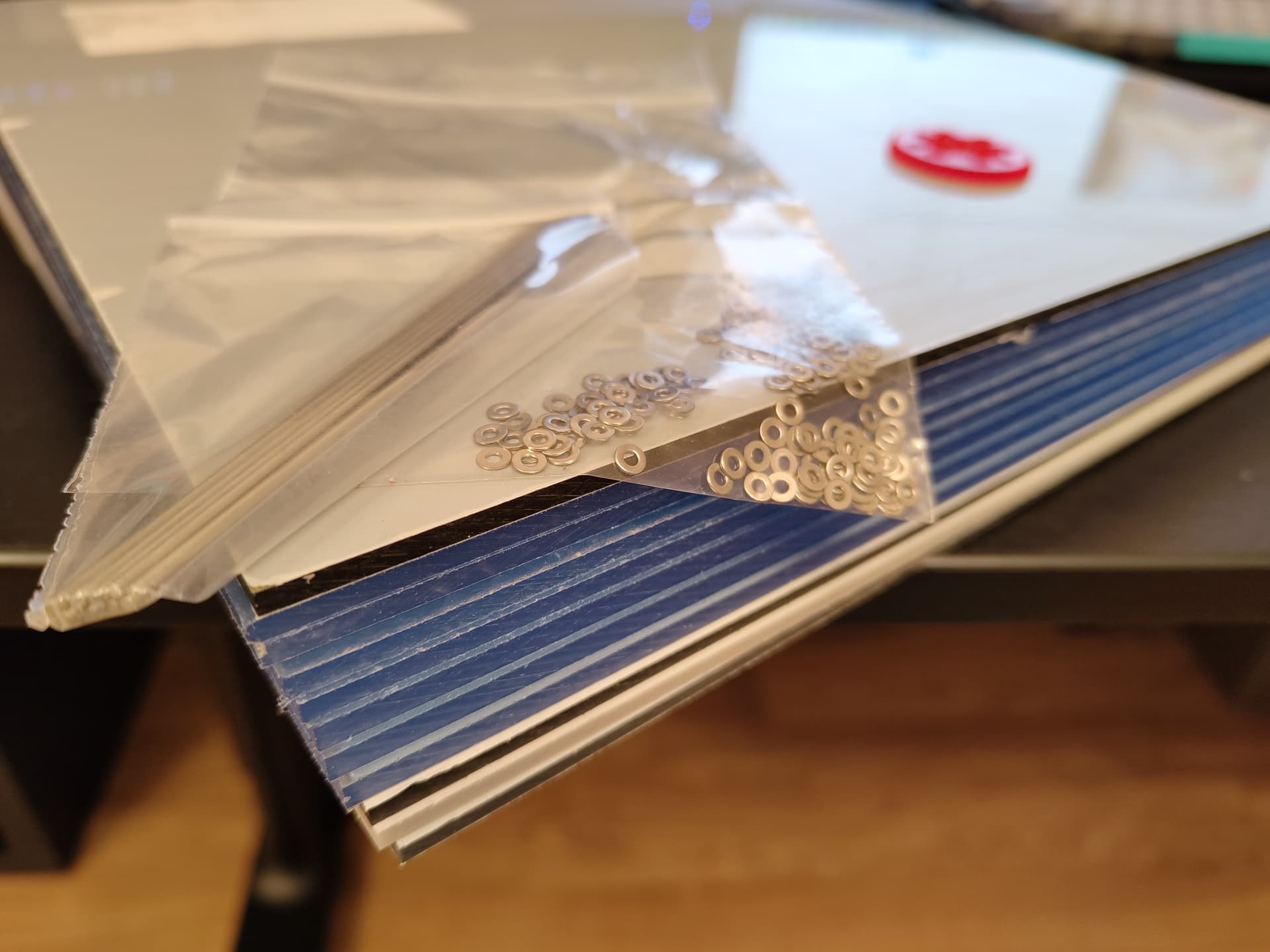
I’ve found some short steel pins for sale so I’m waiting for those and I’m no longer planning to cut the steel rods to their correct size.
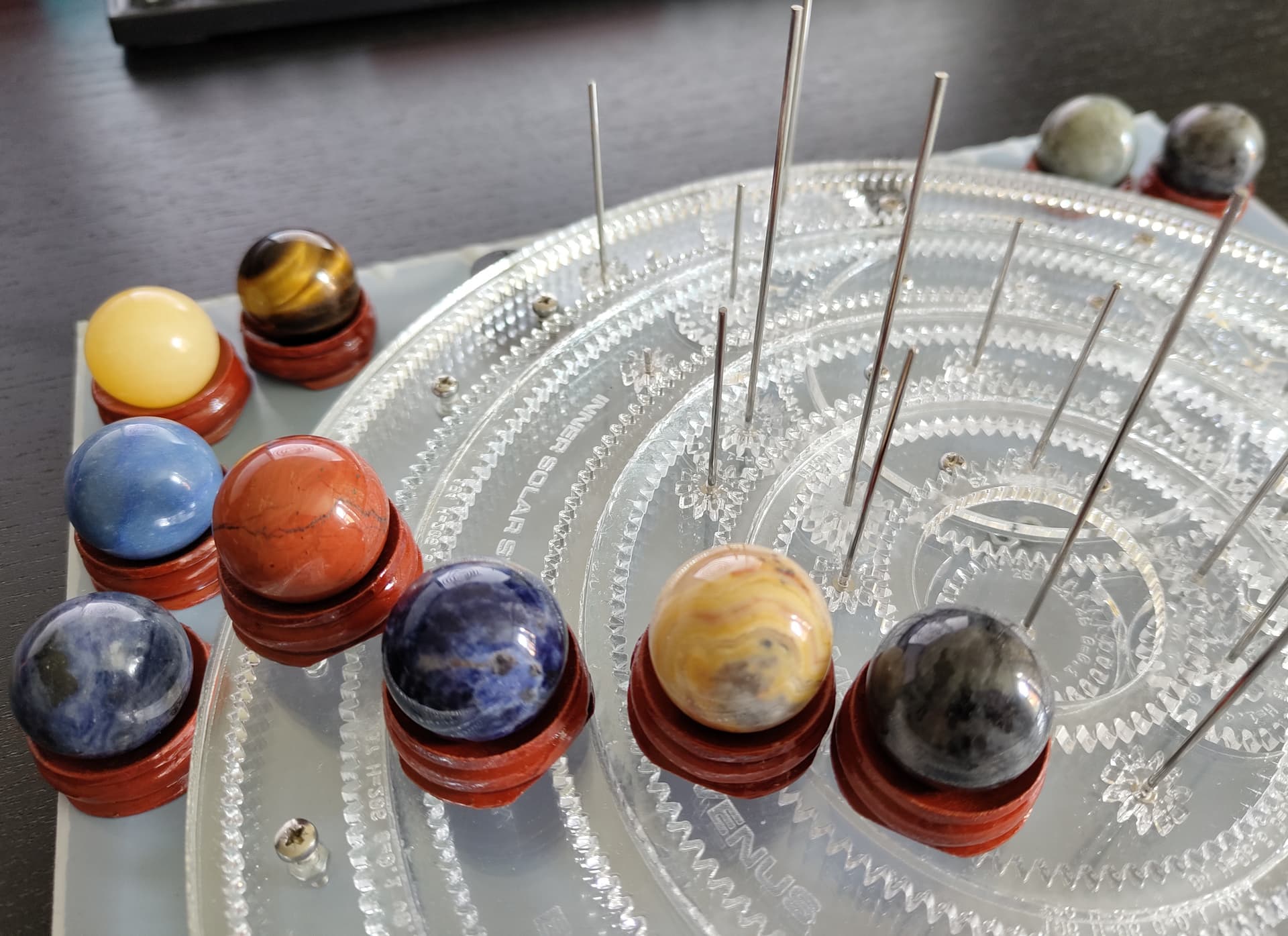
The next steps will be attaching the planets to the steel rods and creating the holders for them that ride on the large gears.
The orrery is looking fantastic, the stone planets really suit it!
I had an idea on the friction for the larger gears - could you change the design to include a number of simple roller bearings around their smooth side rather than using small gears on the toothed side?
I’d imaging the friction would be a lot less, but it would need a larger gap between the big gears to accommodate the rollers.
I’ve been thinking about this as well. It wouldn’t work due to the space requirement like you say.
I think the friction between the base plate and the large gear is the bigger problem, so I thought I could do something like a model railway. If you search for “v groove roller”, some wheels like that and a bent metal plate to roll along the v groove. I’m not sure if that’s necessary or even possible.
I’ve been trying to drill into the stone ball and it’s not working well. When the drill touches the stone, the drill bit moves to the side and the hole is off-center. Maybe there is too much play in the chuck. I want to see if it works better with the lathe but I haven’t figured out how to remove the block in the middle . I’m planning to try again tonight.