Last week I tried unsuccessfully to move a USB port from a MIDI device. Currently, the micro USB port is located on the right side of this Novation Launchpad Mini, which isn’t compatible with the stand it’s going in.
“Easy”, past Jagmills thought to himself, I can just add a cable soldered to the USB socket’s pins and route it out the back, giving me what I need.
Sadly, I’ve failed miserably in this effort - my PC would not “recognise device” when connected to the soldered cable, and so began a fervent and fruitless attempt at getting it to work, which resulted in much Leoing of the original PCB.
Here’s a picture scraped from the internet of the PCB in question:
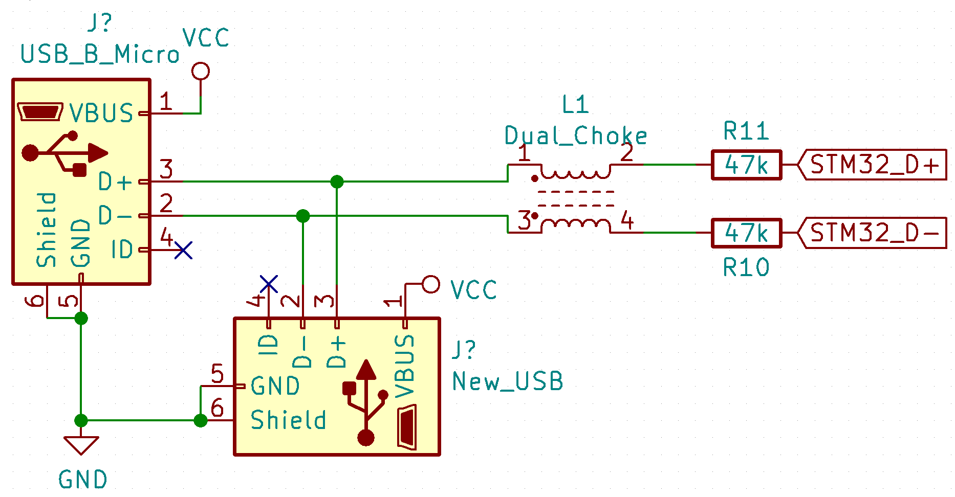
The USB port on the left has 6 pins - shield (grounded), ground (grounded), v+ which goes into the large rectifier thing below it, ID (which was unconnected) D+ and D- which go under the crystal, to a small choke, through two 4k7 resistors and into the STM32.
First attempt, didn’t work. I tried swapping D+/D- as well.
The controller lights up and goes into a ‘screensaver’ mode, indicating it has power (but no data connection). Windows computer reports “unrecognised device”
Third attempt, did some research about this choke and while some datasheets recommend it’s put there to cut down on EMI on the USB lines, it’s not necessary. Thus I soldered the data lines to the resistors directly to ‘bypass’ the choke (but left it in), and still the same behaviour:
Sadly, I am all out of options now. The last thing I considered doing was to remove the choke.
I haven’t found any shorts between the data lines, but does anyone have any suggestions whatsoever of what I can try?
Pull up resistor values. 4.7k in 1st description paragraph, 47k in further schematics. What does it say on the resistors?(similar to ceramic capacitor coding).472 or 473.
Yet more attempts on this, yet more failures.
Sigh.
Not worth making up a schematic but I removed the choke component, still the same problem.
To do this properly, I will probably try one last thing of gluing a small protoboard + header to newly soldered thinner wires to the relevant pads.
I just can’t fathom how I can get two wires so wrong!
Heya! I just found your post through the great cyber network while looking for info on fixing the USB port. I was recently gifted a launchpad mini that doesn’t have a USB port (it broke off and was lost). I don’t have a proper replacement but was going to simply cut off the end of a micro usb cable and solder the four wires to the board and call it a day.
Can I ask you a few questions?
I see the pads where the old port was and am wondering in what order I should solder to them? Will I run into the same issues you are talking about in this thread?
I am new to this specifically but have a lot of experience soldering diy synths and simple circuit bending.