##747-400 Simulator Posts
Part 1
Part 2
##Introduction
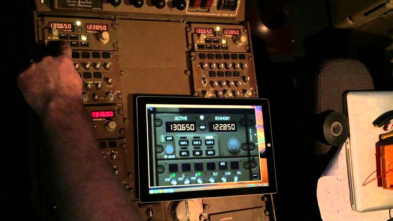
A friend of mine is building a 747 flight deck simulator with the aim of maximum realism. To this end he is using genuine 747 parts interfaced into the simulator software. Most of the switches and indicators on the flight deck are wired up to USB capture cards and interfaced with the multiple simulation servers.

The missing piece of the puzzle was interfacing more complex devices that talk over ARINC 429 protocol. This is where I could help out.

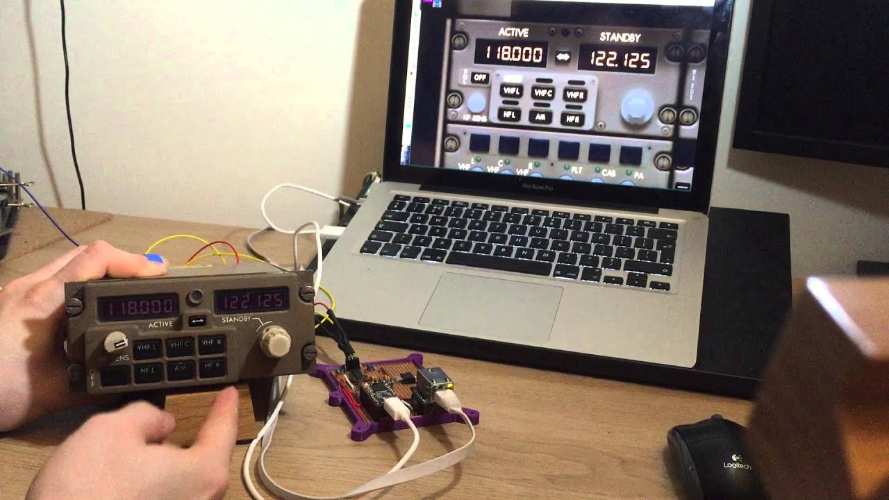
This is a Radio Communication Panel (also known as Radio Tuning Panel). It features 5 frequencies that can be tuned (VHF L, VHF C, VHF R, HF L & HF R). Typically all the ‘L’ are controlled by the pilot, ‘R’ by the co-pilot, and ‘C’ by either, or used primarily for ACARS. There are 3 RCPs in the flight deck that talk to each other over ARINC; it is the comms from RCP L that are being monitored currently.

This is the prototype ARINC to Ethernet converter.
The prototype has 3 areas of interest.
At the top is the part that converts the bipolar return-to-zero ARINC429 signal into logic level SPI signals compatible with a microprocessor.
At the left is the Teensy 3.1 which has been my 32-bit micro of choice for the last year and it is superb. Seriously; forget Arduino.
(Teensy uses the Arduino IDE so its not a big learning curve if you’re Arduino-aware)
Finally on the right is the WIZ820io module which makes it incredibly easy to add Ethernet support to your projects.
##Challenges encountered with this project
- Decoding the ARINC frames; they are 32-bits with a non-standard bit ordering so some swapping of bits in memory was required.
- Providing a robust debug output over the USB serial to make development of decoding for new hardware easier and make this more of a ARINC utility tool.
- The Ethernet section uses the Teensy’s only hardware SPI port, so I had to come up with a novel interrupt-driven software SPI port to receive the ARINC frames.
##Media
YouTube video showing the RCP interfaced with the flight sim software
YouTube video showing the RCP’s installed in the flight deck interfaced with the flight sim software
Conclusion
This project took 2 weekends to do and was extremely satisfying to do. Future plans include interfacing with other ARINC devices and making a PCB.

